LEGO Design
LEGO Technics are fun to play with and allow the construction of interesting structures, but they are not always easy to use. In fact, it is often quite challenging to build a LEGO device that does not fall apart at the slightest provocation. A well-designed LEGO device should be reliable, compact, and sturdy. If it makes extensive use of gears, the geartrain should be able to rotate cleanly and easily. If it is a structural element, it should hold together squarely and resist falling apart. This chapter discusses some ideas for creating a well-designed LEGO structure, as well as some properties of the LEGO Technic system that may not be obvious at first glance. Keep in mind that sometimes the best way to discover LEGO is to explore, focus on the brick, and try new things.
Fundamental LEGO Lengths
Figure 8.1: The Unit LEGO Brick
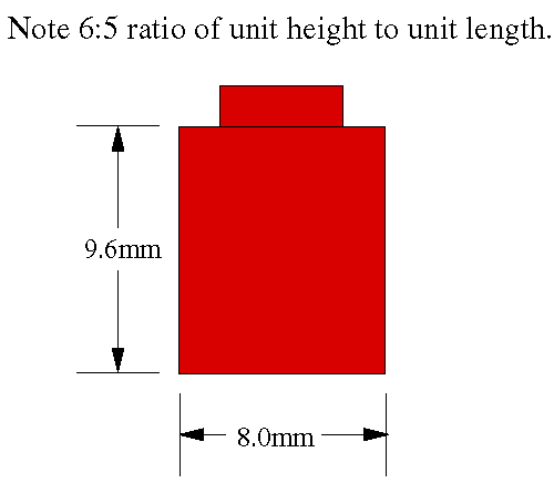
LEGO pieces have standard sizes so LEGO structures are usually multiples of those dimensions. The Fundamental LEGO Unit (FLU) refers to the height of a simple brick, and can be expressed in standard units, such as the millimeter: the vertical FLU is 9.6 mm. Interestingly, the ratio between the length or width of a brick and its height is not an integer, but a ratio of two small integers: 6 to 5 (see Figure 8.1).
Figure 8.2: Perfect 2-Unit Vertical LEGO Spacing
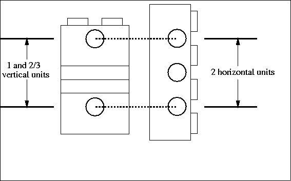
The 6:5 ratio, coupled with one-third height flat pieces, allows the creation of vertical spacings that perfectly match unit horizontal spacings, the spacing between the holes in LEGO beams (see Figure 8.2). By using these perfect LEGO spacings, vertical stacks of bricks can be reinforced with cross-beams, forming sturdy structures that should not fall apart.
Figure 8.3: Clamping Two Beams at Perfect Vertical Spacing
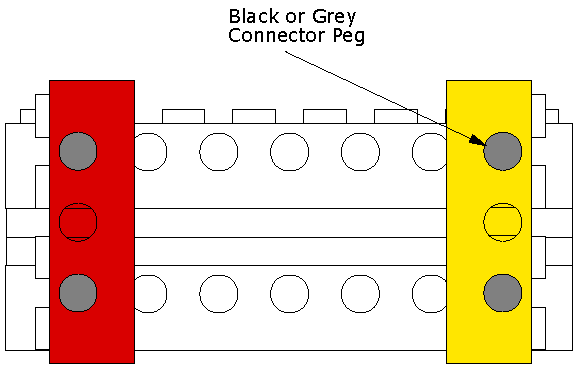
Figure 8.3 shows an example of two 8-long LEGO beams (separated by a two-unit perfect spacing) braced at the ends by two 4-long LEGO beams; this structure is extremely sturdy. Other combinations of perfect vertical spacings are possible with the one-third height bricks; in fact, all of them can be computed. Let a represent the number of full-height vertical units and b the number of one-third height vertical units; then the height of a LEGO assembly (in mm) would be
9.6(a + {13}b) (4)
since a full vertical unit is 9.6 mm high.
The length between holes in a LEGO beam is 8 mm, so if c represents the number of horizontal units between the two holes, then the holes are spaced by 8c mm. To find a match of vertical and horizontal spacings, we need to find values of a , b , and c that make these two quantities equal, with the restriction that a , b , and c are integers (since we cannot use fractional pieces of a LEGO:
9.6(a + {13}b) = 8c (5)
which reduces to
2(3a + b) = 5c (6)
The following table lists some solutions to this integer equation: Bracing LEGO structures using perfect vertical spacings is a key method of building a structurally sturdy machine.
Figure 8.3: Clamping Two Beams at Perfect Vertical Spacing
| Full Height | One-Third | Horizontal |
|---|---|---|
| Units | Units | Units |
 |  |  |
| 1 | 2 | 2 |
| 3 | 1 | 4 |
| 5 | 6 | |
| 6 | 2 | 8 |
| 8 | 1 | 10 |
LEGO Gearing
Making a good LEGO geartrain is, some may say, an art. However, this art can be learned and having some simple information can make a big difference. One of the first things to notice about LEGO gears is their diameter, which indicates at what spacings they can be meshed together.
The natural units for the sizes of LEGO gears is the horizontal LEGO spacing unit. The following table shows the radii of the various LEGO gears:
| Gear Teeth | Gear Radius |
|---|---|
| (number) | (horizontal units) |
| 8 | 0.5 |
| 16 | 1 |
| 24 | 1.5 |
| 40 | 2.5 |
Notice that three of the gears (namely, the 8-tooth, 24-tooth, and 40-tooth) have radii that, when used together in pairs, result in axle spacings that are integer multiples of the fundamental LEGO horizontal unit spacing. For example, the 8-tooth gear may be used with the 24-tooth or the 40-tooth gear, but not the 16-tooth gear.
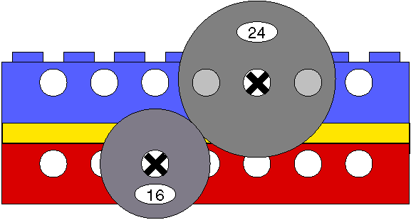
Figure 8.4: Meshing of an 8-Tooth Gear and a 24-Tooth Gear

Figure 8.4 shows how an 8-tooth gear would mesh with a 24-tooth gear along a LEGO beam. The 16-tooth gears only mesh with each other according to this logic.
Gears may be meshed together at odd diagonals. However, this requires great care, as it is difficult to achieve a spacing that is close enough to the optimal spacing (which can be computed by adding the gears' radii). If the gears are too close, they will bind or operate with high frictional loss; if they are too far apart, they will slip. Figures 8.5 and 8.6 show some (but not all) examples of diagonal gearing that have been tested to work well.
Figure 8.5: Diagonal Meshing of an 8-Tooth Gear and a 16-Tooth Gear

Figure 8.6: Diagonal Meshing of a 16-Tooth Gear and a 24-Tooth Gear
When constructing any gearbox, especially those that involve gears meshing at odd diagonals, it is important to keep in mind that although the LEGO gears are very functional in terms of experimenting with various designs, their performance over time is not ideal. Gears meshing in even the most thoughtfully constructed gearbox may begin to wear, and might have a greater tendency to slip under stress. While it is important to develop a sturdy gearbox, it might be wise to keep its parts accessible in the event that a gear needs to be replaced after the robot has been constructed.
A very high performance geartrain will be necessary for driving a robot. For this type of geartrain, the following rules are suggested:
8-tooth and 24-tooth gears should be used. The 40-tooth gears are also good, if they can be fit in despite their large size.
The worm gear can be used to quickly assemble a good geartrain, although worm gears will cause more power loss due to friction than other types of geartrains.
The axles should be spaced at perfect LEGO spacing, or a close diagonal approximation. This is easy to do if the axles are mounted adjacent on the same beam, or across beams using perfect LEGO spacing.
Each axle should be supported at two points by going through at least two girders or beams. These support girders should be separated from each other. If these two rules are followed, the axles will stay straight and not bind up inside the girders, creating a lot of friction.
When multiple girders support the same axle, these girders should be firmly attached to each other. If they are not perfectly aligned, the same binding problem described above may happen, and the gear train could lose a lot of power.
The axles can bend. Gears should not be dangling at the end of an unsupported axle. Gears should either be put between the girders supporting the axles or very close to the girders on the outside of the girders. Both cases are illustrated on the example gear train. If the gear is two or more LEGO units away from the outside of the girders, problems may arise.
Axles should not fit too tightly. After gears and spacers are put on an axle, the axle should be able to slide back and forth a little bit. It is very easy to lose a lot of power if spacers or gears are pressing up against the girders.
Gear Reduction
Gearing serves two main purposes: transmitting and transforming mechanical energy. For the purposes of a drive train, the gears will change the high speed and low torque of a DC electric motor to the low speed and high torque that is required to move a robot. Experimentation with different gear ratios is important. The gear ratio determines the important tradeoff between speed and torque.
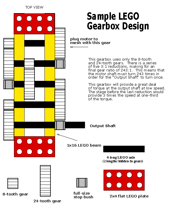
Figure 8.7 illustrates a sample LEGO geartrain that achieves a gear ratio of 243:1 through the use of five ganged pairs of 8-tooth to 24-tooth gear combinations (this gear ratio may be overly high for a robot drive). It is suggested that a copy of this geartrain be built for evaluation -- it is an efficient design and follows the rules presented here.
Figure 8.7: LEGO Gearbox Example
Chain Drives
Use of chain drives requires a fair bit of patience. To find gear spacings that will work for the chain requires a lot of trial and error design. If the chain is too loose, it may skip under heavy load; if it is too tight, it will lose power. Experimentation is required. The chains tend to work better on the larger gears and with fundamental LEGO spacing between the axles. See Appendix A for more information about building a good chain drive.
Differentials
The differential gear is used to help cars turn corners. The differential gear (placed midway between the two wheels) allows one wheel to turn at a greater speed than the other. Even though the wheels may be turning at different speeds, the action of the differential means that the torque generated by the motor is distributed equally between the half-axles upon which the wheels are mounted. Assuming the robot's weight is sufficient and distributed properly, the robot should be able to turn with its drive motors at full power without causing either wheel to slip. In terms of robot construction, this means that one wheel could be completely stalled, while the other would continue to revolve. Because slipping of the wheels is avoided, static friction between the surface and the robot is maintained providing a better translation of rotational force to linear force.
The LEGO kit provided has both simple differential gears as well as two gear differentials. The two gear differentials allow the option of either a 16 tooth or 24 tooth spur gear as the final gear in the drivetrain. The regular differential has a cross between a spur and crown gear with 28 teeth, which requires some creative but not impossible spacing in order to achieve a gear reduction that meshes well.
Though you may decide not to use a differential as a means of transmitting motor force to the drive axles; this does not mean the differential is useless. When placed directly between the wheels of two independently driven drive axles, a differential gear, coupled with a shaft encoder, could potentially be used as a supplementary directional sensor without significantly affecting the operation of the drive wheels. For example, if a vehicle with a differential gear had a drive axle spinning at X revolutions per minute(rpm), the differential housing would be rotating at X rpm as well, so long as the vehicle is moving directly forward or backward. If the vehicle were to pivot about the point exactly in the middle of the drive axles, the differential housing would not rotate, as the bevel gears within the housing would then be operating at full speed. Based on these endpoints and some experimentation, a program could be written to determine the radius of curvature of the vehicle's motion. This method could also be applied to a differential used directly in the drivetrain, but it would be unlikely that the differential housing could be motionless while the drive motor is in action.
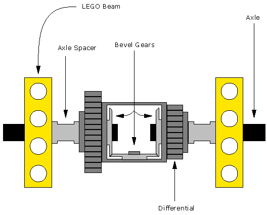
Figure 8.8 shows a simple LEGO differential gearbox.
Figure 8.8: A Simple Differential Gear
Testing a Geartrain
Back-driving is a good way to test a geartrain. The motor should be removed (if it is attached) and a wheel placed on the slow output shaft. When the wheel is rotated by hand make all the gears should spin freely. If the geartrain is very well-designed, the gears will continue spinning for a second or two after the output shaft is released.
Low-Force Geartrains
When building geartrains that will transmit only small forces, many of the design rules do not apply. Some of the usual problems may turn out to be advantages. For example, it may be desirable to have a transmission that "slips" when it is stuck, so that the motors do not stall and then a rubber band and pulley drive would be appropriate. The 24-tooth crown gear -- in addition to being perfectly usable as a normal 24-tooth gear -- will function at the intended 90 degree angle, as long as it is only transmitting small forces.
Rack and Pinion Steering
Rack and pinion steering uses a motor to turn a pinion (a LEGO gear), which then shifts a rack (a flat LEGO piece with grooves corresponding to gear tooth spacing) to the right or left. This allows very precise and smooth steering, especially when using a stepper motor. Figures 8.9, 8.10 and 8.11 show the top, side and front views of a simple LEGO steering mechanism that uses a rack and pinion. It is unlikely that this exact structure would be directly applicable to a working robot; however, it should provide a start.
Figure 8.9: Rack and Pinion Steering (Top View)
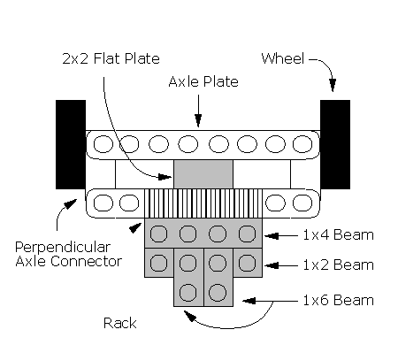
Figure 8.10: Rack and Pinion Steering (Side View)
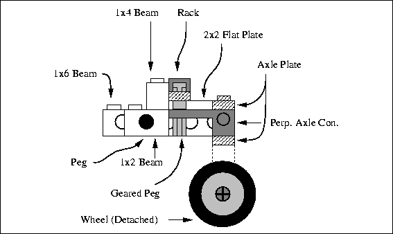
Figure 8.11: Rack and Pinion Steering (Front View)

Multi-tasking Motors
At times, a robot may need to perform seven or more different mechanical maneuvers. This can be a problem as each robot is only able to power six different motors. However, there are ways of exploiting motors to perform multiple functions. Obviously, one motor could be used to drive two separate geartrains simultaneously, but then both geartrains are dependent on each other. If one stalls, then they both stall and it's impossible to turn one off without losing the other one.
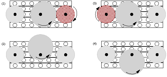
One possible strategy for multi-tasking motors is to place the axle off center. Now the gear is acting like a cam. The drive train will be intermittently broken as the "camgear" and the drive train come in and out of contact. Figure 8.12 shows an example of a LEGO gear cam. One motor could be used to power two gear trains by setting up a "camgear" to intermittently drive one gear then the other (8.13). This approach would be most practical if a gear needed to repeatedly turn part of a revolution and then retract. The cam would turn the gear a partial revolution and a rubber band could be used to restore the original position. It would be a waste of a motor to turn a short distance forward then reverse over and over, and the motion is bound to be inconsistent. Thus if such a motion is desired, using a cam driven by another gear train can be a useful solution.
Figure 8.12: "Camgear"
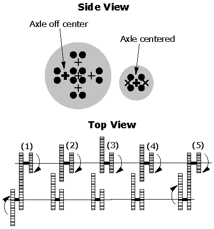
Figure 8.13: Cam driving Two Gears Intermittently
Another possibility for multi-tasking a motor would be to use forward and reverse for different functions. It is possible to drive a motor in just one rotational direction and still be able to travel in reverse. The solution is a mechanical transmission. In Figure 8.14 the drive shaft can be made to turn either clockwise or counter-clockwise depending on which of the large gears is being turned by the motor. One way of selecting which large gear is turning is by using a mechanical transmission like the one shown in Figure 8.15. It is useful to note that the same gear reductions may be achieved for the forward and reverse motions by inserting a gear on a free-spinning axle into the gear reduction. The size of the extra gear is immaterial with regards to the gear reduction, so the appropriate gear size would depend only on convenience and a proper meshing distance between gears.
Figure 8.14: Bi-directional Drive Train
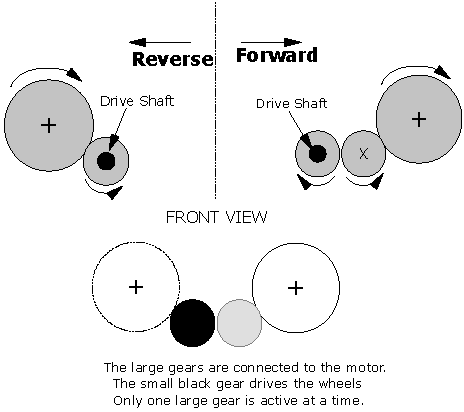
Figure 8.15: Mechanical Transmission Prototype
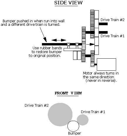
The manual transmission shown in Figure 8.15 is only a prototype. The idea is to be able to use forward and reverse from a single motor for separate tasks. The details of an actual implementation are left up to you. In the setup shown, driving into a wall moves a gear from one gear train to another, perhaps allowing the robot to change direction without changing the direction in which the motor rotates. One problem is how to move forward again. Simply using a rubber band or spring to return to the original gear train, not enough time will have passed to allow the robot to back away from the wall very far. With a bit of ingenuity and mechanical experimentation, it is possible to multi-task motors.
source : www.owlnet.rice.edu
No comments:
Post a Comment